Blog
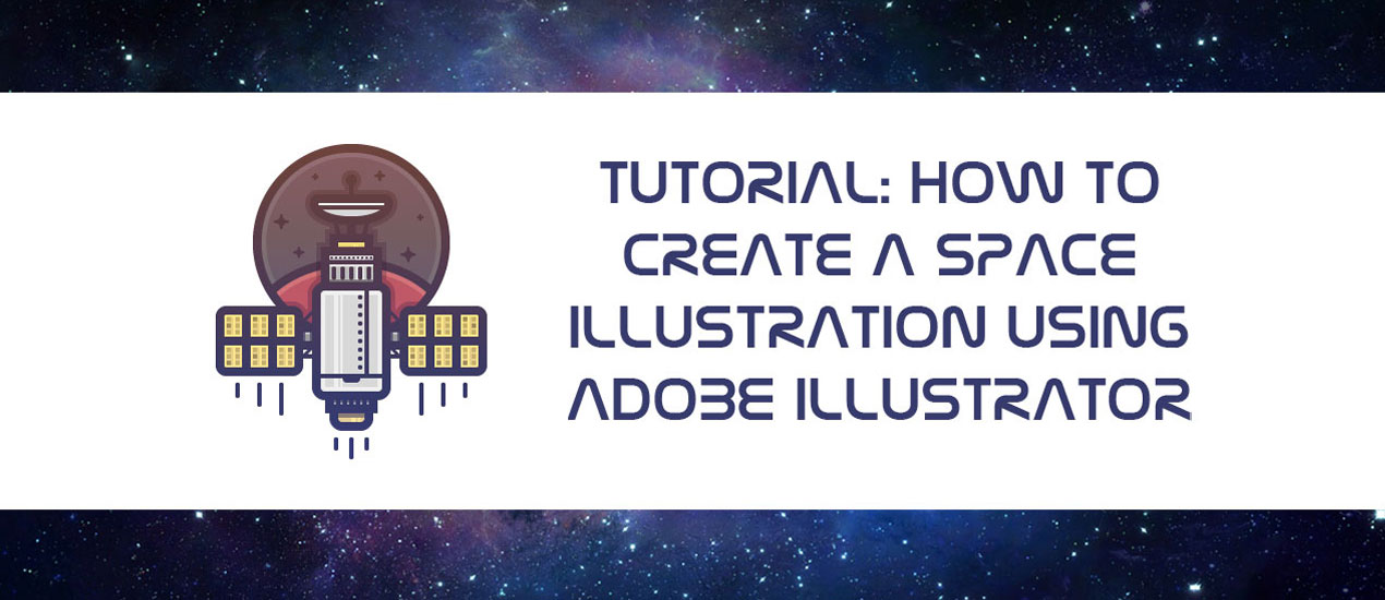
Tutorial: How to Create a Space Illustration Using Adobe Illustrator
Space has and will probably always be one of those things that man has long dreamt of conquering. From the darkest corners of the Milky Way to the farthest region of the known Universe we will always poses that urge to explore and look for new worlds, worlds that could change what we know about life itself.
The recent space missions that NASA has successfully accomplished made me want to do a little tutorial that would pay homage to all the hard work that has been put into the deep exploration of these unknown regions surround our little blue home.
So, in the following lines, I’m going to walk you through the process of creating a neat looking illustration using Adobe Illustrator.
Adobe Illustrator Illustration Tutorial
1. Setting Up Our Document
This is probably one of those important things that you need to pay attention to when starting out a new project, since you’ll want to set up a correct working space from the start instead of having to fiddle with the settings later on.
So, assuming you already have Illustrator up and running, go to File > New, or use the Control-N keyboard shortcut, and let’s go through some of the settings for this project:
Number of Artboards: 1
Width: 800 px
>Height: 600 px
Units: Pixels
And from the Advanced tab:
Color Mode: RGB
Raster Effects: Screen (300 ppi)
Align New Objects to Pixel Grid: checked
2. Layering Our Document
Usually when dealing with a large composition, where you have a lot of elements I find it easier to layer the document so that if I need to edit a specific part of my illustrations, I can do that without having to worry that I’ll accidentally tinker with something else without knowing which could lead to issues later on. Also it’s far faster to have things separated on layers since you don’t have to create tons and tons of grouped objects and go back and forwards into Isolation mode since you can easily select and adjust the shapes and paths using far lesser steps.
Now, for our current project, I’ve created three layers and named them as follows:
- background
- satellite
- overlay
As you can see I tried to use easy recognizable key words so that there are directly referencing a piece / section of the illustration, thus letting me know exactly what I have on each of my layers.

3. Adjusting the Grid
If you’ve ever took a look at Illustrator’s Preference settings, you might have noticed that it gives you the option to set up a custom grid, which would allow you to fine tune the movement of your shapes once they are Snapped to the Grid. As you know, even though vectors are scalable they are still pixel dependent, which means that if you want to create crisp looking artwork you’ll have to snap your shapes and paths to the Pixel Grid. I won’t go over the process of creating pixel perfect artwork since I’ll be writing a separate piece on that in the following months, what I’ll do is show you the settings that I use on a daily basis.
First, let’s go over to the Edit > Preferences > Guides & Grid and as you can see a little popup window appeared giving us a bunch of options. The ones that we are interested are the Gridline Every and Subdivisions ones. These control the precision level that Illustrator uses to snap things to its pixel grid.
So what that means is that if we want things to be as crisp and sharp as possible we will have to go with the smallest values for the two options which is 1 px and 1 subdivision.

Once you’ve adjusted these settings, you’ll still have to go to the View menu and enable the Snap to Grid option which will make the Custom Grid active.
Also, if you’re used to moving things around using your keyboard’s directional arrow keys, you might want to took a look at the Keyboard Increment settings and adjust the default value to 1 px which will make things move with super high precision.

4. Creating the Illustration
At this point we should have a well-oiled machine which means we can leave all the technical stuff aside and get creative.
We will start by building the satellite segment of the illustration first, which means that we will start with the second (middle) layer, and lock all the other ones so that we won’t place parts of the composing elements on one layer and then a couple on the other two by mistake. Think of it as a general rule, every time you start working on a specific part, lock all the other layers so that you can focus only on what’s at hand at the present moment. Then, once you’ve finished working on that section, lock its layer, and then move on to the next section making sure to unlock its layer so that you can work on it.
4.1. Creating the Satellite Section
Step 1
First, make sure that you’re on the right layer, and let’s start by building the satellite’s main body. For that we will be using the Rounded Rectangle Tool, which can be found underneath the Rectangle Tool which is located on the left toolbar. Select it, and then click anywhere on your Artboard to create a custom sized shape with 56 px Width and a 92 px Height and a Corner Radius of 4 px. Color the shape using a dark grey (#D8D8D8) and then correctl position it onto the Artboard by entering the following coordinates into the Transform Panel’s X and Y value fields:
- X: 400 px
Y: 336 px

By using these values, you will make sure that you’ll follow as close inside my footsteps as possible when it comes to creating and positioning your satellite, since at the end it will be positioned almost if not exactly as mine.
Also, since we want everything to be snapped to the Pixel Grid make sure to check the Align to Pixel Grid option found at the bottom of the little panel.
Step 2
Now that we have our main shape positioned, we can start adding details, and we will do so by first adding an outline.
With the shape selected, go to Object > Path > Offset Path > and enter 8 px into the offset value field from the pop window.
This will create a copy of your selected shape which will have both its Width and Height slightly increased by 8 px and will be automatically positioned underneath the original shape.

Step 3
Now, since this will act as an outline, we need to change its color to something darker so that it can reflect that visual function.
To do that simply select the shape and change its grey tint to a darker one using this hex value #363A3D.

Step 4
Since our satellite will have a couple of little detail elements such as the screws, vertical and horizontal delimiting lines, and highlights we have to plan ahead and think of how these elements will be layered. Now, since the highlights will actually go underneath the delimiting lines we will have to create them now, so that we won’t have to select things and send them to the back later.
So first create a copy (Control-C > Control-F) of your satellite’s fill shape (the grey one) and then create another smaller 48 x 84 px rectangle which we will position over the fill shape and use to create a cut out.
Once you have the rectangle in place, select both it and the grey copy and use Pathfinder’s Minus Front option to create the ring like shape that we will use as a highlight.

Step 5
Adjust the resulting shape by going over to the Transparency panel and setting its Blending Mode to Overlay while lowering its Opacity level to 60%. As you can see we now have a nice looking ring like highlight, which means that we can start adding the two vertical ones.

Step 6
Grab the Rectangle Tool (M) and create a wider 4 x 84 px rectangle and a narrower 2 x 84 px one which we will adjust by using the same Blending Mode and Opacity level. Distance the two at about 2 px from one another, and then position them towards the left side of the satellite’s body.

Step 7
We will continue focusing on adding the details and we will do so inside of the Pixel Preview mode, since it will allow us to see exactly where we position our shapes, giving us a better control over the spacing of our elements.
So, first go to View > Pixel Preview to turn it on, and then zoom in on your illustration, and using the Rectangle Tool (M) draw a 4 x 76 px shape (#363A3D) which we will position towards the right side of the main body, since it will act as the vertical delimiter. Make sure that the top section of the delimiter touches the top side of the main body’s outline.
Then, add a 56 x 4 px rectangle (#363A3D) which will act as the horizontal delimiter, which we will position just underneath our vertical one, making sure to horizontal align it to the main body.

Step 8
Next, let’s add the little screws, by creating nine 4 x 4 px circles (#363A3D) which we will distance at 4 px from one another, and then position onto the left side of the vertical delimiter, leaving a gap of 2 px between them.

Step 9
Add a little pocket right underneath the horizontal delimiter by creating a 16 x 8 px rounded rectangle (#363A3D) with a Corner Radius of 4 px which we will horizontal vertical align it to the top side of the horizontal line. Once you have all the elements of the satellite’s main body, it might be a good idea to group them so that you won’t accidentally move them around. To do that, simply select them all, and then use the Control-G keyboard shortcut.

Step 10
Move a little towards the bottom and start working on the satellite’s rear section by creating a 32 x 4 px rectangle (#9B9B9B) and then giving it a 8 px outline to keep things consistent. Make sure to position the two so that the outline overlaps the one of the satellite.

Step 11
Add a subtle shadow to the top section of the smaller satellite component, by creating a 32 x 2 px rectangle which we will color using black (#000000) and then adjust by lowering its Opacity level to 40%.

Step 12
Continue adding details to this part of the illustration by creating five 4 x 4 px squares (#363A3D) which we will position over the fill shape and shadow, at a distance of 2 px from one another.

Step 13
Start adding some color to the illustration, by creating the gold plated bottom section of the satellite using a 24 x 16 px rounded rectangle with a 4 px Corner Radius which we will color using #E5CF76. Then give it an 8 px outline and position both it and the outline underneath the previously created section of the satellite (select them > right click > Arrange > Send to Back), so that the two outlines overlap.

Step 14
Add a shadow and two vertical highlights using the same process that we followed for the satellite’s main body, only this time instead of using white for the highlights and adjusting the Blending Mode and Opacity simply use a lighter gold color (#FFE67D).
Then once you’re done with this section, group all of its elements using the Control-G shortcut.

Step 15
Let’s move on up towards the top section of the satellite and start building the actual parts and pieces responsible for the transmission and reception of the data.
First, grab the Rectangle Tool (M) and draw a 40 x 24 px shape, which we will color using #BCBCBC and then position just above the main outline of the satellite’s body. Then give it an 8 px outline, so that it won’t fall flat.

Step 16
Next, add a horizontal delimiter line towards the top side of the new segment, by creating a 40 x 4 px rectangle (#363A3D) and positioning it so that you have a gap of 4 px between it and the top main outline.

Step 17
Start adding a couple of highlights and a bottom shadow in order to give it some more depth.

Step 18
Add a couple of decorative elements by creating ten 2 x 2 px circles (#363A3D) distanced at 2 px from one another, which you will position in-between the top side of the satellite’s segment and its horizontal delimiter. Then add five 4 x 12 px rounded rectangles (#363A3D) with a 2 px Corner Radius, distance them at 4 px from one another, and then position them underneath the horizontal delimiter.
As with the previous segment, don’t forget to group all of its elements together using the Control-G command.

Step 19
Add another gold plated segment by creating a 24 x 4 px rectangle (#E5CF76), give it an 8 px outline, and then add a top and two vertical highlights (#FFE67D).

Step 20
In the next part, I’m going to let you get a little creative and come up with an antenna system of your own. So, take your time and build something cool and interesting to give the illustration a little personal touch.

Step 21
Next, we will start working on the satellite’s solar “wings” by creating the arms that hold them in place.
So, grab the Rectangle Tool (M) and create a 8 x 8 px rectangle (#9B9B9B), then give it an 8 px outline and position the two on the left side of the satellite making sure to vertical center align them to its main body.

Step 22
Add a couple of side shadows and a top highlight to the little arm section.

Step 23
Now since we can’t start working on the metal grid system that adds extra structure to the solar panel’s arm, until we have the solar panel itself, we will have to start working on that segment.
First, create a 64 x 48 px rounded rectangle with a 2 px Corner Radius, color it using #E5CF76 and then give it an 8 px outline using the Offset Path tool, making sure to align the two shapes to the satellite’s main body.

Step 24
Start adding some details to the panel by creating the ring like highlight (#FFE67D), and then adding a couple of vertical and horizontal delimiters to create six smaller solar sections. Once you have the delimiters in place start adding some more highlights so that each of the six solar section is lighten on each side.

Step 25
Next, start adding six 4 x 4 px squares to each of the six solar sections coloring most of them using #C6AF4E, and a just a couple using #A08C38 to give them a little visual pop.
Then, finish the panel by adding a vertical highlight to each of the six segments and grouping all of its components together (Control-G).

Step 26
Now that we have the solar panel, we can start working on the metal grid that adds to the stability of the satellite’s arm.
Using either the Pen Tool (P) or Rectangle Tool (M) draw a couple of lines (#363A3D) that would look strong enough to hold that solar panel.
Once you’ve done that, select both the solar panel and the arm and its grids and group them together, since in the next step we will create the right solar “wing” using a copy after it.

Step 27
Select the left solar “wing” and create a copy (Control-C > Control-F) and then reflect that copy by right clicking and then going to Transform > Reflect and choosing Vertical from the Axes option.
Then simply drag the shape to the right side of the satellite and position it in place.

Now, as you can see at this point we’re pretty much done with the satellite section of the illustration, which means that we can now move on to building the little background.
4.2. Creating the Little Background
So, assuming you’ve already locked the previous layer and positioned yourself onto the background one, we can now start by creating the little background depicting a little red planet and some far distanced stars.
Step 1

Step 2
Add an all-around circular highlight to the fill section of the background, using Overlay as the Blending Mode and an Opacity of just 20%.

Step 3
Start working on the little red planed by drawing a 174 x 124 px ellipse which we will color using #BF5858 and then give it both an outline and a circular highlight making sure to position the three composing shapes towards the bottom section of the little background.

Step 4
Now as you can see, the planet actually goes outside of the background’s surface, which is something that we would prefer it to not. To fix this, we will have to create a copy (Control-C) of the background’s fill shape (the purple-ish one) and paste it (Control-F) over the three grouped shapes. Then with both the red planet and the copy selected right click and select Make Clipping Mask to hide all the parts that we don’t want to show.

As you can see, we now have our little planet perfectly tucked inside the background circle.

Step 5
Once you have planet, we can start adding a bunch of little starts around the satellite’s antenna communication system. Take your time, and build a couple of size variation which you will color using the same tint that we’ve used for the outlines (#363A3D).

Step 6
To give the illustration more depth, we will create a shadow around the section of the satellite that overlaps the circular background. To do that, simply select and create a copy after those shapes and then paste them over to the satellite layer and give them a 4 px outline. With all the shapes still selected, unite them using Pathfinder’s Unite function, and then change their color to black (#000000) and set the resulting shape’s Opacity to 20%.
Then as with did with the red planet mask it so that the shadow won’t go outside of the circular background.

Step 7
Add a little movement to the illustration by adding a couple of lines underneath the solar panels and the bottom golden plated section of the satellite.

At this point we’re pretty much done with the illustration itself. All there is to do now, is add the little overlaying gradient to give it that nice visual effect.
4.3. Adding the Subtle Overlaying Gradient
Step 1
In order to add the gradient we must first, grab a copy of the main shapes of our illustration (usually the outlines) and paste them onto the gradient overlay layer. Then select all the shapes and create a Compound Path by going to Object > Compound Path > Make. Since the gradient needs to be uniformly applied using a Compound Path is a must.

Step 2
Once you’ve created your compound, all there is to do is go to the Gradient panel and create a Linear gradient with a -90 angle, and select orange (#F15A24) for the left color and blue (#0000FF) for the right one.

Step 3
Finally, change the gradient’s Blending Mode to Lighten and lower its Opacity to 30% in order for the illustration to come to life.

It’s a Wrap!

That was it guys! If you’ve followed my steps you should have created a pretty nice looking illustration that you can use in future projects. Thanks for attention and see you next time!